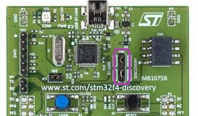
Programming Bluepill via Stm32f4-discovery If you have that handsome guy : bluepill and do not have stlink programmer, also you have a discovery board, "What a low probability for this article to be read." -but ok, I am the one, faced with this situation maybe some other one also can be. 😁 Step1 : Removing St-Link Jumpers There are two jumpers on area labelled CN4, (marked in purple square) if they are jumped like on the picture, this means embedded st-link programmer can program discovery board, if you remove them, st-link programmer connection to discovery MCU is removed and free to use externally. Step2 : Connecting St-Link Pins to BluePill There are six pins on the area called CN4, marked in the picture. The pin numbers starting 1 from top and go down to 6. We just use 1 to 4 pins. If you want to reset your bluepill via button on the discovery board you can connect NRST to Reset pin of Bluepill. Anyway, the pins of bluepill : B...
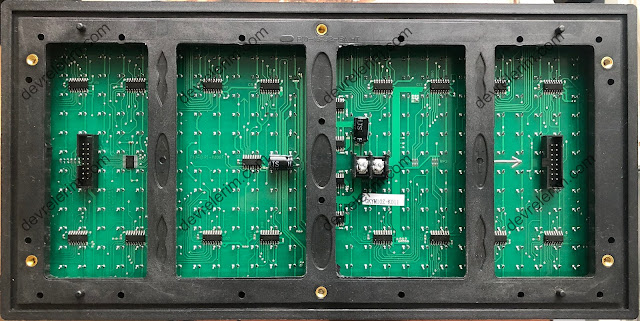
P10 Led Panel 32x16 consist of 512 leds. There are 2 connectors, called Hub1.2 (8x12 male header) and 5v power connector. Hub1.2 placed left side of the board shown in image below is input, right one is the connector to connect another p10 panels input. Pin definition of Hub1.2 is shown in image. ENABLE pin is the pin which allows you to control the panel is working state or stop state. Panel enables when it is driven a HIGH signal, When it is driven low it does not matter another pin states, panel stops working. A, B are row selectors, this pins represent a 2 bit binary number allow you to select one of four rows in a sequence. Selecting a row means that, the leds on the selected row are powering their anod pins. There are 16 rows in total(A1-A16), and they are in a group of 4. Each group of rows are represented with the same color in the images below. Look at the table, driving A and B with a LOW signal means selecting rows labelled A1,A5,...
Let's code! Expalantions are in the code area. Happy Coding! /* * DHT 11 driving without library * * http://en.devrelerim.com * Author : Hakan OZMEN (hakkanr@gmail.com) * Date : 30.03.2021 * * You can change or share all / or same part of * this code. Free of charge! :) */ uint8_t data [ 5 ] ; // to save our 8bit * 5 data void setup ( ) { Serial . begin ( 115200 ) ; } /* * This function count an 8bit integer value * while given signal is not changed * no need to measure time counting is also * need time ;) */ uint8_t expectedSignal ( bool level ) { uint8_t count = 0 ; while ( digitalRead ( 2 ) == level ) count ++ ; return count ; } void loop ( ) { delay ( 2000 ) ; // wait 2 secs for sensor to initialize Serial . println ( "----------------------" ) ; pinMode ( 2 , INPUT_PULLUP ) ; // Standard is HIGH delay ( 1000 ) ; pinMode ( 2 , OUTPUT ) ; // make pin 2 output...

Comments
Post a Comment
You can share your experience, or ask anything about the topic, Let's write ;)