Posts

Showing posts with the label working principle

How does P10 Led Panel Work? | Working Principle and calculations

Image
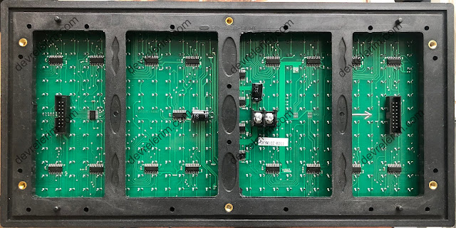
  P10 Led Panel 32x16 consist of 512 leds. There are  2 connectors, called  Hub1.2  (8x12 male header) and 5v power connector. Hub1.2 placed left side of the board shown in image below is input, right one is the connector to connect another p10 panels input. Pin definition of Hub1.2  is shown in image.  ENABLE pin  is the pin which allows you to control the panel is working state or stop state. Panel enables when it is driven a HIGH signal, When it is driven low it does not matter another pin states, panel stops working. A, B are row selectors, this pins represent a 2 bit binary number allow you to select one of four rows in a sequence. Selecting a row means that, the leds on the selected row are powering their anod pins. There are 16 rows in total(A1-A16), and they are in a group of 4. Each group of rows are represented with the same color in the images below. Look at the table, driving A and B with a LOW signal means selecting rows labelled A1,A5,A9 and A13.  B A Selected rows

Working Principle of DHT Sensors and Analysis with Logic Analyzer

Image
 What's inside DHT11 sensor , I've removed the plastic case and what I saw is :     There is a resistive type humidity measurement component, a NTC to measure temperature and a 8 bit microcontroller and it uses single-wire serial interface to communicate  with other systems. Measurement range 0-50 °C in temp and 20-90%RH in humidity. Accuracy for temp is ±2°C, ±5%RH for humidity, and last information about it is resolution is 1.          What about the power? it can work between 3v and 5.5V, this means you can use it 3.3v boards and also 5v boards. Communication Process      This is the part I like the most !     - One communication process is about 4ms.     - Data format : 8bit Humidity (integer part) 8bit Humidity (decimal Part) 8bit Temp (integer part) 8bit Temp (decimal Part) 8bit checksum totally we have 40 bits of data to deal with. Let's look at the signal on data pin with logic analyzer     There are two timing maker pairs A1 to A2 (at the same point B1),

How does DHT11 sensor work?

Image
     In this article, we are looking for how DHT series sensors work and how can we drive them without using any library. Especially about DHT11 sensor here in this content. DHT 11 is a very cheap way to measure temperature and humidty in embedded systems, like arduino or STM based development cards      You can see two types of DHT11 sensor which one have 3 pins with a board, another is just sensor. Difference between two is just a pullup resistor, If you have alone one, you should put a 10K resistor, signal pin to VCC pin to made them the same, there is no any difference except alone one has an unsused pin !?     This Sensor can be used with Adafruit's DHT sensor library , with a requirement which is Adafruit's Unified Sensor Library. You can find them Library Manager on Arduino IDE . It's very easy! Just click Tools * Manage Libaries, you will face with Library manages which has a text box Fill your search... written.  Text there DHT Sensor and find DHT Sensor Library