Working Principle of DHT Sensors and Analysis with Logic Analyzer
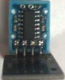
What's inside DHT11 sensor, I've removed the plastic case and what I saw is :
There is a resistive type humidity measurement component, a NTC to measure temperature and a 8 bit microcontroller and it uses single-wire serial interface to communicate with other systems. Measurement range 0-50 °C in temp and 20-90%RH in humidity. Accuracy for temp is ±2°C, ±5%RH for humidity, and last information about it is resolution is 1.
What about the power? it can work between 3v and 5.5V, this means you can use it 3.3v boards and also 5v boards.
Communication Process
This is the part I like the most!
- One communication process is about 4ms.
- Data format : 8bit Humidity (integer part) 8bit Humidity (decimal Part) 8bit Temp (integer part) 8bit Temp (decimal Part) 8bit checksum
totally we have 40 bits of data to deal with.
Let's look at the signal on data pin with logic analyzer
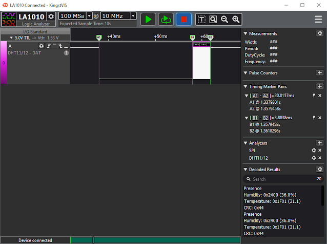
There are two timing maker pairs A1 to A2 (at the same point B1),its about 20ms. first one is to wake up DHT11 sent by the MCU (arduino or STM such boards) on this period, DHT 11 changes own mode from low-power consumption to the running mode and waiting mcu to complete (HIGH) the signal. After that(MCU sets the signal High), MCU is waiting DHT to make signal LOW to understand DHT ready to send data. This means DHT says to the system, Hey! Be ready I am sending the data now!
Here is the signal part, its from B1 to B2 about 3.89ms.
Single bus data free status is HIGH as you understood, of course there is another clue that it has a Pull-up resistor 😎
Let's try to understand what does this waveform tell us, there is two types of pulse. one is wider than the other, and there is no magic I can notice, narrow one means 0 wider one means 1, that's the way how we can get the data. In theory narrow one should be between 26-28us but, when I measure on the waveform it's about 24.7 ~ 24.8µs and we can accept it as zero if it's less than 30µs. Wider one is about 70µs and it's the same the waveform, the times I've given are ON time (HIGH state).
Now let's look at the zeros and the ones. They are respectively:
The first 8 bits were the integer part of the relative humidity value
1st 8 bits: 0010 0100 ok it'is in binary system, it's 36 on 10base.
The second 8 bits are decimal part of relative humidity
2rd 8 bits: 0000 0000 it's zero I've never seen there is any one, so no decimals in humi.
The third 8 bits are integer part of temperature
3rd 8 bits: 0001 1111 and it's 31 in 10 base
The fourth 8 bits are decimal part of temperature
4rd 8 bits: 0000 0001 and it's just 1
whole data in this waveform is 36.00 humidity and 31.1 temperature.
Ok! what about the checksum bits. It's also easy to underand. There are some Math! Sum all of the data come, value you find is the CRC!
36 + 31 + 0 + 1 = 68 => 0100 0100 in binary. This makes us sure about we've gotten the data correctly.
That's all! now time to code.. see you next part


Comments
Post a Comment
You can share your experience, or ask anything about the topic, Let's write ;)